
AST0801 Foldback wedge
-tn.JPG) |
If you are on
a budget, after a compact good sounding wedge and have the
woodworking skills required. Then the AST0801 will do a better job
than many, if not all of the lower cost Foldback wedges on the
market. As an indicative price I made a set of 6 of these wedges for under $500 (Australian dollars) each. This is a woodworking project so with the exception of the crossover I do not have it in kit form so you will need to find the parts yourself. |
Anyone who runs smaller systems, would be aware that lower Frequencies from foldback are often clearly audible to the audience, usually in the form of a muffled sound that muddies the Front of house sound.
This muddy sound is generally in the frequency range below 300Hz and the irony is that usually Singers and musicians do not need to hear much of this through their foldback and often what they do want to hear bleeds back from Front of House anyway.
The upshot of this is that there is little or no point designing a foldback speaker that goes significantly below 150Hz - OK possible exceptions here, are for things like Drum fill, but for Vocals (the main requirement for Foldback), Guitars and keyboards, Foldback does not typically require much bottom end.
Another common issue (particularly with less expensive Foldback wedges) is that it is often possible to hear that the Tweeter and woofer are in different places, this can be very disconcerting especially if the performer moves around at all. I have been meaning to play around with Co-axial drivers for a while and this design gave me an ideal opportunity.
While the crossover took a bit of fiddling to get sounding nice the final version was surprisingly much simpler than I had anticipated.
Before we go on - all woodworking dimensions here are given in Millimetres.
click on any pictures or diagrams for a closer look.
Parts required:
B&C 8CX21 8" Co-axial speaker
17mm void free Plywood - 1 x 1200 x 2400mm (4 foot by 8 foot) sheet is enough for 6 wedges
9mm Plywood
2 x cabinet mount Speakon sockets
8 x 3/16" Tee nuts (I could not get Tee nuts in metric)
8 x 3/16" by 25mm long Bolts
2 x 1/4" Tee nuts
2 x 1/4" by 25mm long Bolts
4 x 1/4" Washers
Tube of 'Liquid nails' or equivalent Builders glue.
Senseal or equivalent epoxy Resin
Lamp or Carbon Black
Hard wearing paint
Plastic wood or 'Builders bog' (unless you are far better at wood work than me)
Passive Crossover
1.5mm2 insulated wire - two 1.5m lengths in different colours should do
Cutting up the wood:
I got the wood from a local 'Mr Plywood' store. In order to make it easier to transport, I got the wood pre cut - note they do not cut angles, which meant that I still had more cutting to do when I got the wood home.
For anyone interested I had them cut up the wood as per the following Diagram:
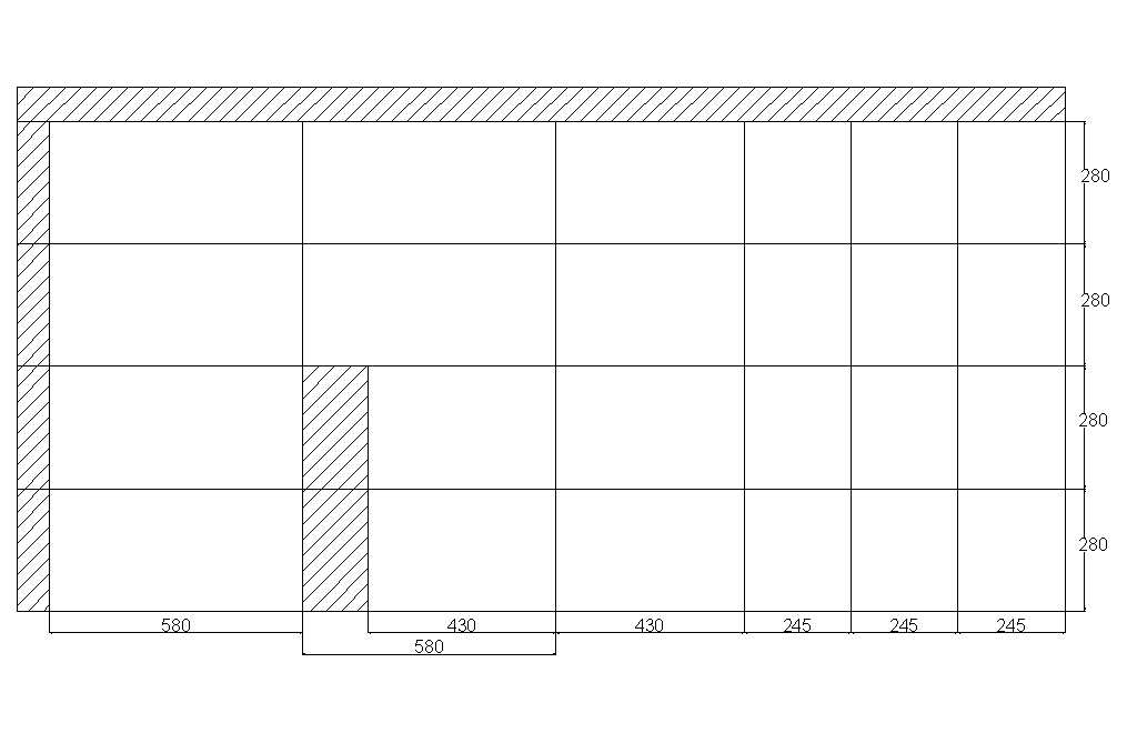 |
Cut up the 580 x 280mm sheets into smaller pieces for the body of the wedge these will need to be cut at an angle - note the cut between piece A and B is 15 degrees from vertical and the cut between C and D is 30 degrees while the cut between B and C is vertical (as per the side view at the top of this picture):
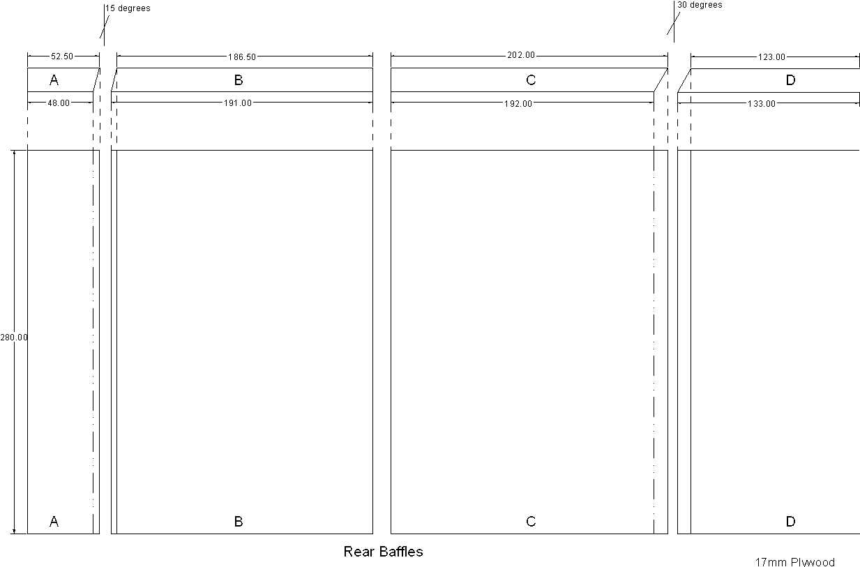 |
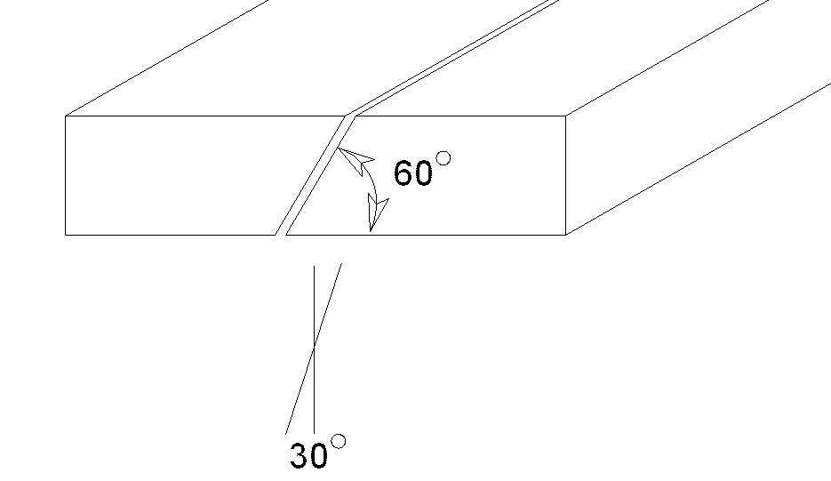
While cutting wood at an angle take the long offcut (from the top of the panel) and cut it lengthwise down the middle at an angle of 30 degrees.
this should give you two lengths of wood about 2400mm in length and somewhere near 30-40mm wide.
 |
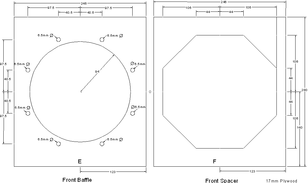
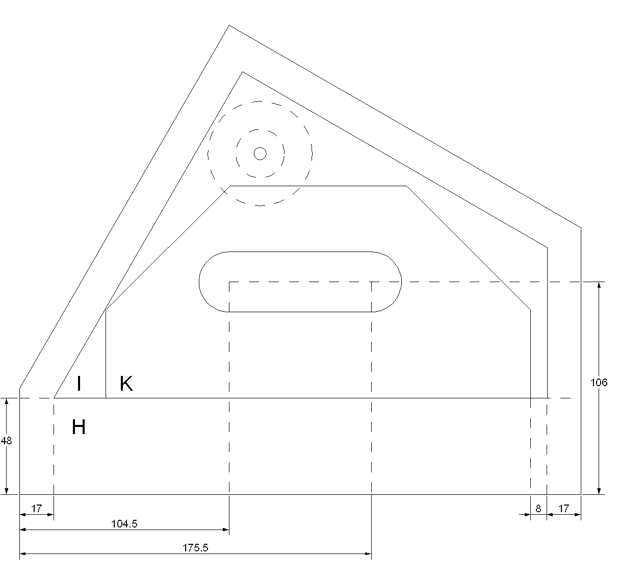
The 430 x 280 pieces become the side panels and these require very careful measurement.
Note: do not drill or cutout the handle, connector holes or speaker stand mounting holes at this stage, merely drill small pilot holes (say 3mm or 1/8th inch) to mark the centre of each circular hole.
 |
 |
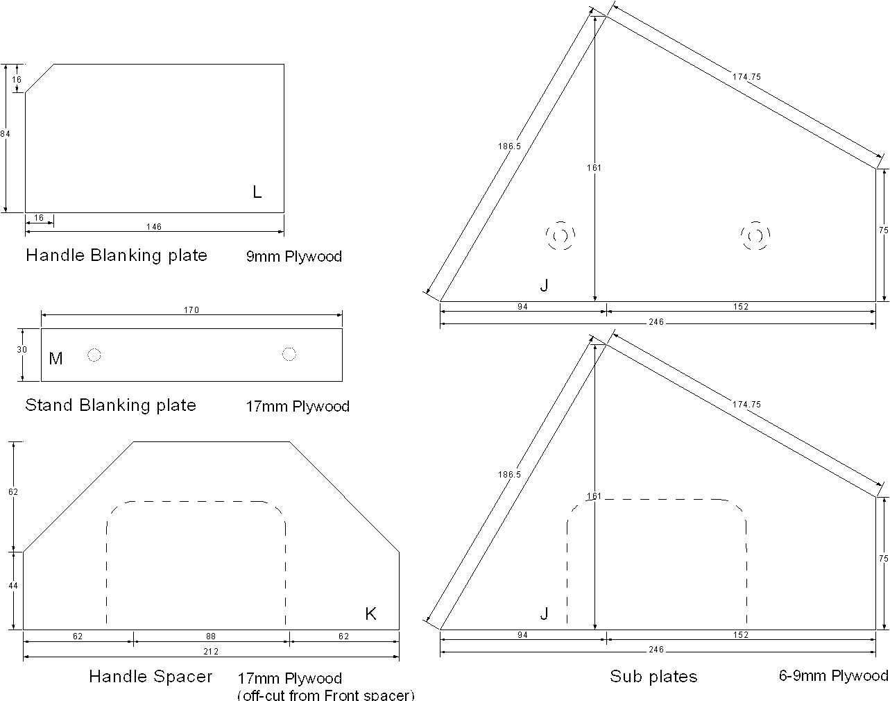
The Subplates and Handle blanking plate can now be cut out of 9mm ply wood, the Handle spacer is made from the offcut from the Front spacer and the stand blanking plate (if you choose to add the speaker stand option) can be made using any other 17mm offcuts.
 |
Assembly:
First step is to screw together the Sideplates and Subplates - DO NOT GLUE them together yet.
 |
With the plates and subplates assembled drill the pilot holes for the connectors, handle and speaker stand mount (if you want this option).
Next screw on the Handle spacer and using a hole saw cut two 30mm Holes through the Sideplate, Subplate and handle spacer.
 |
 |
 |
 |

|
NOTE: These photos are for illustrative purposes only - I have made an error with my measurements in these pictures as the Subplate and Handle spacer are mounted 53mm back from the front edge - they should in fact be 5mm further forward.
If you have a long enough Jigsaw then you can finish cutting out the handle with all the parts assembled - my Jigsaw was not long enough so I had to cut the handle out of the sideplate separately to the Subplate and Handle spacer.
 |
 |
 |
 |
 |
Get the parts for the other sideplate
If you want the speaker stand adapter mount then attach the stand blanking plate and drill out the pilot holes - NOTE drill the pilot hole into, but NOT all the way through the stand blanking plate.
Disassemble and cut out the 52mm hole for the connector through the sideplate and a 25mm hole through the subplate.
Using a 16mm spade bit (speedbore or equivalent) counter sink the mounting holes on the outside of the Sideplate about 4-6mm should be adequate - you want the countersink to be deep enough so that the heads of the mounting bolts do not stick out of the hole.
Also countersink or drill through the subplate using a drill large enough to push the T nuts into.
Next drill out the holes in the sideplate using a drill large enough so that the T nut is a tight fit.
Using the same Drill drill into the Stand blanking plate - NOTE Do not drill all the way through -about 10mm depth should be fine.
 |
|
 |
 |
 |
Page 2
Kit costs $xx (Australian) and includes:
PCB for Crossover only
If there is enough demand I may start stocking the B&C 8CX21, however I am afraid most folk outside of Australia will be able to source these more cheaply than through me
Assembly instructions
Email for more details or Paypal instructions (to order) - note at this stage I will have to work out mail costs on a case by case basis...
Copyright © 2011 Australian Technical Production Services